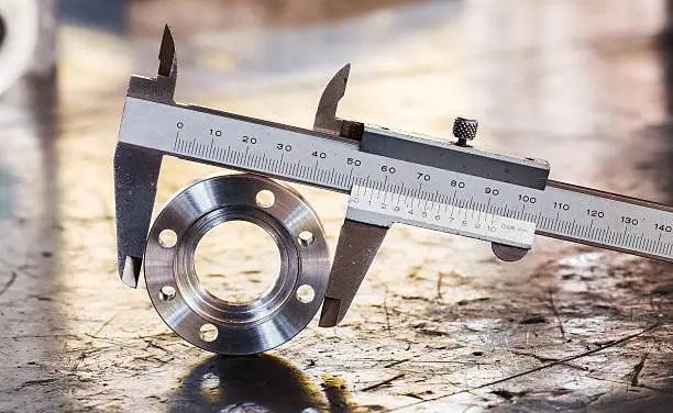
Understanding ISO 286 Hole Tolerances in CNC Machining
Imagine trying to fit a key into a lock; if the key is too big or the lock too small, it won't work. This is the challenge engineers face when designing parts with holes, where ISO 286* standards guide the precise sizing of cylindrical surfaces, and the choice between clearance and interference fits, as well as hole versus shaft systems, are crucial for ensuring seamless assembly and optimal performance in complex machines.*(The ISO 286 standard consists of two parts: ISO 286-1 shaft tolerance standards governing shaft tolerances, and ISO 286-2 tolerance specifications covering hole tolerances in detail.)
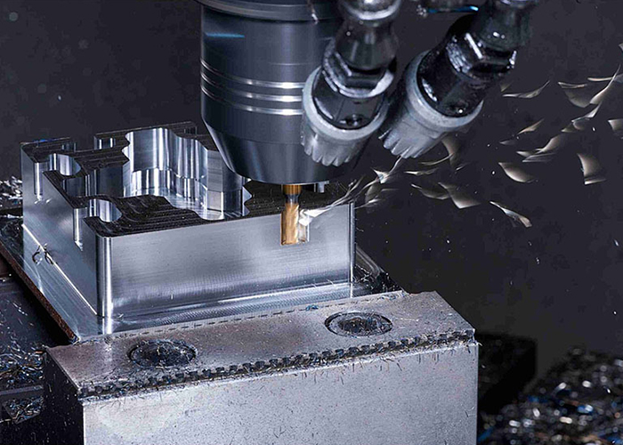
Impact of Tool Wear on Tolerances
Tool wear in machining is like a pencil gradually losing its sharp point as you write. As cutting tools dull over time, they can significantly affect the ability to maintain tight tolerances:
- Worn tools create larger holes and less precise dimensions1.
- Dull edges may cause uneven or jagged surfaces on parts.
- Tool wear can lead to increased cutting forces, potentially causing deflection.
- Surface finish quality often degrades as tools wear down.
To combat these effects, machinists must regularly inspect and replace tools. Some advanced CNC machines use adaptive control systems to automatically adjust for tool wear during operation, helping maintain tolerances even as tools gradually dull. Proper tool management is crucial for consistently achieving tight tolerances, especially for precision parts like those used in aerospace or medical devices.
Hole Tolerance Basics
Hole tolerance in mechanical design is like setting rules for how much a cookie cutter can vary in size while still making cookies that fit nicely on a plate. It's all about ensuring parts fit together properly, even with tiny variations in manufacturing.
- Hole tolerances are specified using a letter-number code, like H7 or F8.
- The letter indicates the position of the tolerance zone (H is common for holes).
- The number represents how precise the hole must be (lower numbers mean tighter tolerances).
- Designers choose tolerances based on the hole's function - a loose fit for easy assembly or tight fit for precision.
- Tighter tolerances generally increase manufacturing costs but improve part performance.
Selecting the right hole tolerance is crucial for ensuring parts work together smoothly, like puzzle pieces fitting just right. Too loose, and parts may rattle; too tight, and assembly becomes difficult or impossible.
ISO 286 for Cylindrical Surfaces
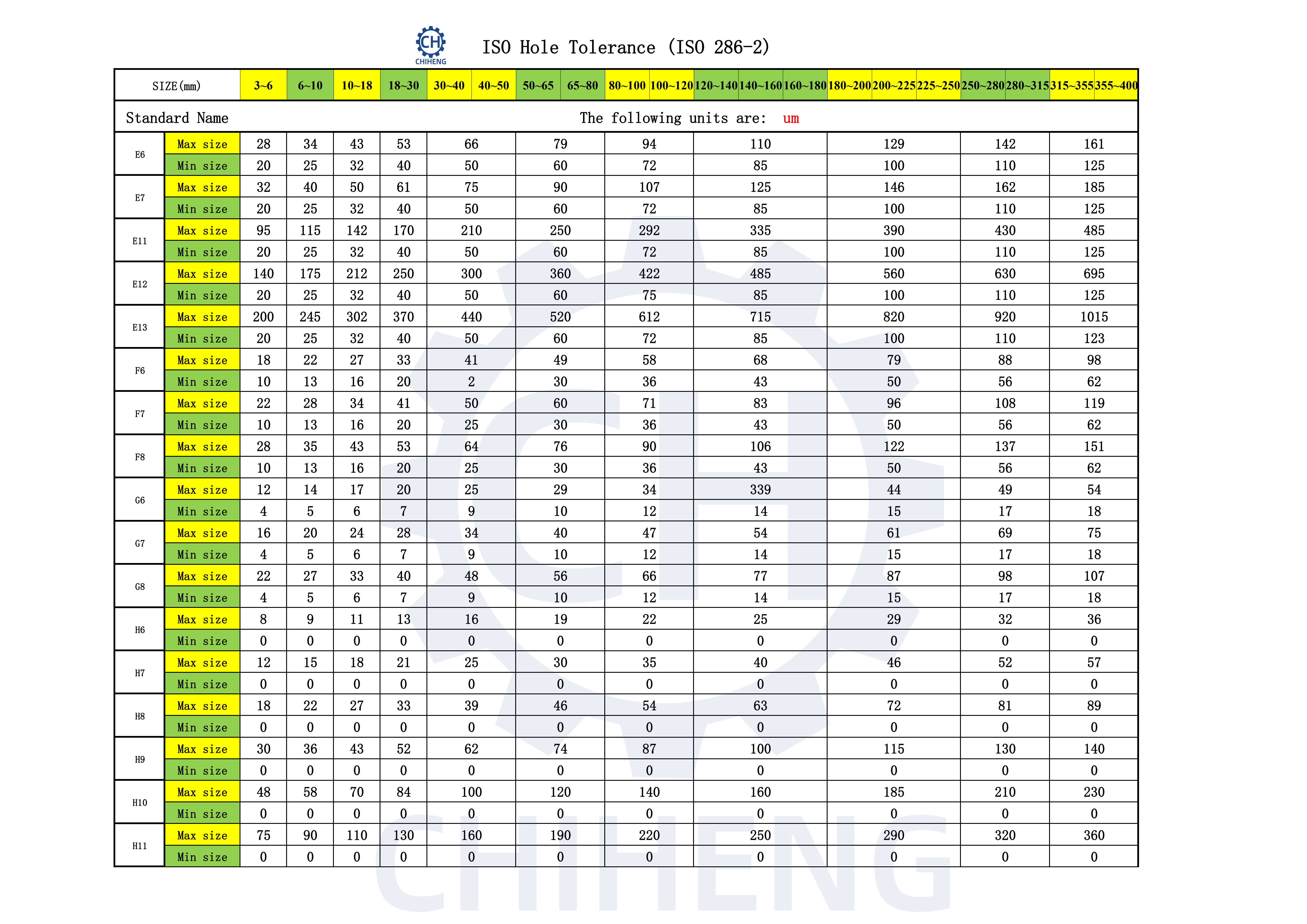
ISO 286 is like a universal language for engineers when it comes to sizing cylindrical parts, such as shafts and holes. It's the rulebook that ensures parts made in different factories can fit together perfectly, like Lego bricks. This standard focuses on two main types of features: cylinders (like shafts) and two parallel opposite surfaces (like the sides of a key)
- It provides a code system for tolerances, similar to shirt sizes (S, M, L) but much more precise
- The standard uses letters and numbers to specify how much a part can deviate from its ideal size
- For holes, uppercase letters are used (e.g., H7), while lowercase letters are for shafts (e.g., h7)
- The number after the letter indicates the precision level, with lower numbers meaning tighter tolerances
- This system helps engineers communicate exact fit requirements, ensuring parts work together seamlessly in complex machines
Hole vs Shaft Systems
Hole Basic System vs Shaft Basic System
The hole basis system and shaft basis system are two approaches to specifying fits between mating parts, like choosing whether to adjust your shirt size or your body size to get the perfect fit. Here's a quick comparison:
| Aspect | Hole Basis System | Shaft Basis System |
|---|---|---|
| Reference Part | Hole dimension is fixed | Shaft dimension is fixed |
| Adjustable Part | Shaft size is varied | Hole size is varied |
| Preferred Usage | More common in industry | Less common, used in specific cases |
| Manufacturing Ease | Easier to adjust shaft size | More challenging to adjust hole size |
| Typical Notation | Uppercase letters (e.g., H7) | Lowercase letters (e.g., h6) |
| Example Application | Bearings, bushings | Custom shafts, some large machinery |
The hole basis system is generally preferred because it's easier and more cost-effective to adjust shaft dimensions through grinding or turning operations. However, the shaft basis system can be advantageous in certain situations, such as when working with standardized shafts or in applications where precise hole sizing is more feasible.
Clearance vs Interference Fits
Clearance and interference fits represent two fundamental approaches to joining components in mechanical engineering, each with distinct tolerance requirements. Here's a comparison of these fit types:
| Aspect | Clearance Fit Tolerance | Interference Fit Tolerance |
|---|---|---|
| Definition | Ensures a gap between mating parts | Ensures overlap between mating parts |
| Tolerance Zone | Hole always larger than shaft | Shaft always larger than hole |
| Assembly Method | Parts slide or rotate freely | Requires force or heating for assembly |
| Typical Applications | Bearings, pistons, sliding mechanisms | Gears on shafts, press-fit bushings |
| Tolerance Calculation |
Maximum Clearance = HLH - LLS Minimum Clearance = LLH - HLS |
Maximum Interference = LLS - HLH Minimum Interference = LLH - HLS |
| Common ISO Designation | H7/g6 (for standard clearance) | H7/p6 (for light interference) |
Understanding types of fits and their applications is crucial in mechanical engineering. In clearance fits, the clearance hole's lower limit (LLH) is always larger than the shaft's upper limit (HLS), ensuring a gap. This allows for free movement, which is essential in applications like journal bearings or piston-cylinder assemblies. The tolerance fit specifications are calculated to maintain this clearance across all possible manufactured sizes.
Press fit tolerance characteristics are different, as these fits require the shaft's lower limit (LLS) to be larger than the hole's upper limit (HLH). This creates an overlap, resulting in a tight, often permanent connection. The tolerance interference fit is commonly used when parts must resist rotation or axial movement, such as wheels pressed onto axles.
The selection between clearance and interference fits depends on the assembly's functional requirements. While clearance fits facilitate easy assembly and disassembly, accommodate thermal expansion, and enable lubrication, press fit tolerance designs provide strong, vibration-resistant connections but may require specialized assembly techniques and can be challenging to disassemble.
Engineers must carefully evaluate factors including material properties, operating conditions, and manufacturing capabilities when specifying tolerance fit parameters. For example, a clearance fit might utilize an H7 tolerance for the hole and a g6 tolerance for the shaft, while a tolerance interference fit might employ H7 for the hole and p6 for the shaft. These standardized designations ensure consistency across various manufacturing environments.
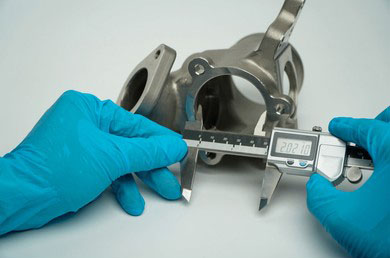
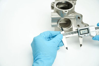
CNC Hole Precision
CNC machining is like a high-tech cookie cutter, capable of creating holes with incredible precision. When it comes to hole tolerances, CNC machines are the superheroes of the manufacturing world, typically achieving tolerances of ±0.0002" (0.005 mm) for standard operations. This level of accuracy is akin to hitting a bullseye from 100 yards away!
- CNC milling and turning can both achieve ±0.0002" tolerances for holes
- For ultra-precise needs, specialized CNC processes can go even tighter
- Tighter tolerances generally mean higher costs and longer production times
- Material choice affects achievable tolerances - metals are usually easier to machine precisely than plastics
While CNC machining excels at creating precise holes, it's important to remember that tighter isn't always better. Like choosing the right wrench for a bolt, selecting appropriate tolerances balances function with manufacturing efficiency and cost. Maintaining consistent hole tolerances across production runs presents significant challenges. Advanced measurement strategies can help manufacturers achieve reproducible results.


